


Eric Rahne, B.Sc. in Electrical Engineering, Level 3 Accredited Thermography Expert (PIM Ltd.)
Thermal imaging devices (thermal cameras) suitable for contactless temperature measurement have undergone rapid development in recent years. Considering that these devices appeared just 50 years ago, but have now grown into one of the most well-known and versatile inspection tools, it is no wonder that the market offers a wide variety of options.
Consequently, for a client planning to procure a thermal camera, the issue is no longer the lack of types that meet their needs, but rather the overwhelming variety of choices available. Therefore, it is time to review the development and types of these instruments from a professional perspective, and organize the current offerings based on some important technical parameters. The measurement technology implemented in the cameras and the accessories available determine the device's application area, as well as the expected measurement accuracy and the achievable thermal image quality.
In the case of matrix detector thermal cameras, thousands of individual sensors are arranged in a matrix-like manner to simultaneously detect the thermal radiation to be measured, eliminating the need for a mechanical scanning unit. Thus, the camera is mechanically simple, compact, and lightweight. Although the optical path is surprisingly simple, the devil is in the details: a major issue is that each pixel of the thermal image is converted by an individual sensor, whose characteristics may closely resemble those of its neighbors but still measurably differ. Compensating for this lack of uniformity requires a significant amount of real-time image processing and automatic NUC (non-uniformity correction). Modern matrix detector thermal cameras, depending on the sensor technology used, can achieve a thermal resolution of 30mK (or even 20mK) today, which is sufficient for most applications.
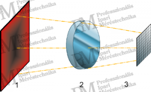
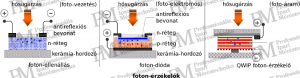
Basically, we distinguish two fundamental types: thermal sensors and photon detectors. Thermal types are based on the principle that they heat up due to the infrared radiation (energy of electromagnetic waves), causing a change in one of their electrical parameters, from which the necessary electrical signal can be extracted. Photon detectors, on the other hand, provide an electrical signal proportional to the number of photons, but their operation requires cooling to deep temperatures (-150°C ... -200°C). (Without cooling, disordered electron movement would hinder the occurrence of the exploitable physical effect.)
Thermal Detectors

Photon Detectors (Quantum Detectors)
Various sensors for different wavelength ranges are available for each sensor technology, depending on the material used. However, it is important to note that the sensor's wavelength range (spectral sensitivity) significantly influences the application areas of the thermal camera. (As a reminder: due to the atmospheric transmission properties, different - limited - wavelength ranges are necessary for thermal cameras. Short, mid, and long-wave thermal cameras are produced for the so-called atmospheric windows. While it is not possible to measure the temperature of low-temperature objects (e.g., -80°C) with mid-wave 3 ... 5 µm thermal cameras, it is impossible to detect objects behind glass with long-wave 7.5 ... 14 µm thermal cameras, for example.
Additional application-related limitations arise concerning large (several hundred meters) measurement distances: these can only be achieved with long-wave thermal cameras. On the other hand, the detection of flame temperatures in combustion processes can usually only be done with mid-wave thermal cameras, but the reverse task - detecting object temperatures through flames without sensing the flame temperature - can be achieved with long-wave thermal cameras. Many applications - such as detecting the temperature of thin foils, gas leaks, or measurements through special measurement windows (e.g., vacuum chamber windows, furnace measurement windows) - require selecting the appropriate wavelength range thermal camera and suitable infrared filters based on the material. Such tasks require special knowledge and experience, and to avoid costly mistakes, it is advisable to entrust them to a professional.
Thermal cameras equipped with bolometer-based matrix sensors exist with frame refresh rates of 9, 15, 30, 50, 60, 120 Hz, or even 240 Hz - regardless of whether they are installed or portable thermal cameras. Significantly higher - up to 9000 Hz - frame refresh rates (more accurately thermal image measurement frequencies) can be achieved with photon detector thermal cameras. The required frame refresh frequency depends on the time constant of the temperature change of the object to be measured, the speed of movement, or even the camera's movement speed.
In any task, the refresh rate of a thermal camera is critical if the "frequency" of thermal changes is twice as fast as the frame rate (Shannon). For example, if the change to be recorded has a period of 1/10 of a second, then a minimum of 20 Hz (preferably 25 Hz) refresh rate is needed. For instance, in the case of power electronics, heating up to 300 Hz can occur, which can only be recorded with a refresh rate above 600 Hz. This can only be solved with a photon detector, just like sensing heat effects during machining, monitoring the temperature of car airbags, researching pyrotechnic processes, or examining impacts of mechanical nature.
The list should not lead to the mistaken conclusion that in the case of slow (or even steady-state) thermal processes, the refresh rate of the thermal camera could not be critical for the measurement. In the case of bolometer thermal cameras, the integration time that determines their refresh frequency limits how fast moving objects can still be correctly detected. The maximum speed of movement is when during the integration time, the surface of an object detected by a single detector extends at most in the direction of motion, so that this "projected" sensing surface does not "run out" from the object surface during the integration time.

Zoomed in on the running legs (the slowly moving body and the left leg on the ground are sharp, the hands and the right leg in fast motion - blurred)
Numerical example:
If we want to detect a 15 mm wide object with a thermal camera with a 30 Hz refresh rate (thus typically with an integration time of about 25 ms) and a 2 mrad geometric resolution from a distance of 1 m, then the maximum speed between the thermal camera and the object (parallel to the object surface) can be calculated as follows:
2 mm + 25 ms * x m/s < 15 mm, where x is the maximum speed of movement
Therefore, based on the above equation, the maximum speed of movement is 0.52 m/s, which is only 1.87 km/h.
Another problem arises when we want to take detailed thermal images or even measurements at greater distances with a handheld thermal camera. It is a well-known fact in photography that a practiced - steady-handed - photographer can take motionless photos even at a 1/60 shutter speed (without a tripod), while an "amateur" may produce occasionally blurred images at a 1/125 shutter speed. These shutter speeds represent an exposure time of 17 ms and 8 ms, respectively. How much skill is needed then to record motionless measurements with a 15 or even just a 9 Hz thermal camera, where the camera needs to be held still for 30 ... 40 ms!
In other words, to capture motionless thermal images, thermal cameras with integration times shorter than 15 ms are needed, which generally have a refresh rate of at least 50 Hz. Thermal cameras slower than this are unsuitable for handheld recordings.

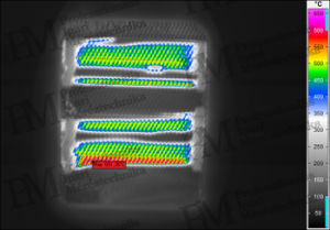
In addition to geometric resolution, the "detail" achievable with a thermal camera is determined by the number of pixels in the thermal camera. The reason is that for graphic recognition, a certain minimum number of pixels must fall on different parts of the object being measured - just as we are used to in digital photography. Therefore, with more pixels, we can represent the object surface with greater detail or the same level of detail over a larger object surface in a single thermal image. If the number of pixels is low, many images need to be taken, and for the evaluation of contiguous objects and the preparation of reports, often the images need to be montaged (which is a time-consuming task).
For thermal cameras, this issue is not insignificant. While in digital cameras we talk about resolutions of 10, 12, or even 20 megapixels (20 million pixels), in matrix thermal cameras, the number of pixels is typically 320x240 (thus 76,800) or 384x288, and in the most professional thermal cameras, 640x480 (thus 307,200) or even 1024x768 (thus 786,432) pixels. There are also cameras with lower capabilities (a common type is 160x120 - thus only 19,200 pixels), which are therefore only capable of displaying smaller areas with acceptable detail, which naturally severely limits their area of application. It is interesting to note that the price per pixel of the most professional thermal cameras with a 640x480 or 1024x768 pixel sensor matrix is much more favorable than that of low-resolution - so-called Low-Cost - thermal cameras.
The following figure illustrates the impact of the number of pixels on the efficiency of the work process: the thermal image on the right (640x480 pixels) was taken with a single press of a button and - since it includes the entire side of the inspected building - can also be easily inserted into the report with just one action. In contrast, the thermal image on the left (160x120 pixels) can only capture a smaller part of the building side, leaving much to be desired in terms of detail. To achieve the quality of the thermal image on the right, 16 times as many shots would be needed, and even for the montage of thermal images, overlaps are required. Therefore, we are forced to take significantly more - up to 20-25 thermal images - which naturally takes much longer compared to the 640x480 pixel thermal image.
However, the real inconvenience awaits us during the protocol preparation, as we face the 20-25 thermal image montage time requirement, which depending on our skill can be 30 minutes, but even several hours. Therefore, it is worth considering whether to choose a thermal camera with a lower pixel count for a smaller investment (and then pay for our savings with multiple additional work), or to acquire the tool necessary for efficient work by opting for a thermal camera with a higher pixel count.

Software-based resolution enhancement with interpolation
Due to the relatively small number of pixels in thermal cameras, creating impressive thermal images (and consequently reports) poses great challenges, especially with thermal cameras having a lower pixel count sensor matrix. To alleviate this problem, some thermal camera manufacturers apply interpolation commonly used in graphic programs. This method inserts an additional - mathematically generated - pixel between each pixel pair of the captured thermal image, thus increasing the pixel count of the thermal image fourfold (by doubling horizontally and vertically). However, this method results in a thermal image containing 75% calculated - thus not real - pixels. Therefore, the application of this method is not recommended.
Software-based resolution enhancement utilizing hand tremor
Considering that a sensor matrix is not composed of individual sensors placed seamlessly next to each other, but there is a (almost half-pixel) gap around each sensor (to avoid thermal crosstalk and due to the electrical connection of individual sensors), the detection of the measured object also occurs in such a "gappy" manner. To address this issue, in recent years, another software-based thermal image pixel resolution enhancement method has started to become popular (e.g., under the names Super Resolution or UltraMax). These methods are based on the slight horizontal and vertical field of view shifts caused by the tremor or movement of the hand holding the thermal camera.
The method is very simple: instead of one thermal image, the data of 16 thermal images are stored, and then, with the help of software, we select the four images that "fit" together due to the hand tremor causing a precise half-pixel horizontal and vertical shift, and then we merge the thermal images pixel by pixel. With this method, even the empty space between two elementary sensors (pixels) results in data, and the number of pixels horizontally and vertically doubles compared to the original detector matrix pixel count - our thermal image becomes four times more detailed. Moreover, as the field of view detection is now seamless, the thermal camera's geometric resolution also improves (by exactly 34%).
As simple (and inexpensive) as this method is, it also comes with pitfalls. It cannot be used with a tripod-mounted thermal camera, and the software rarely finds four images among the stored 16 that can be aligned as described earlier. (Consider that the entire process takes close to one second: if our hand tilts or continuously moves during this time, there is no way to obtain the 4 alignable thermal images.) Furthermore, the software algorithm is unable to select images if the thermal image lacks significant and sharp contrasts (sufficiently steep temperature gradients) or if there is displacement within a part of the field of view.
In the above cases, the software - unfortunately, without any warning - applies the resolution enhancement described during interpolation to achieve the desired pixel count. This results in the creation of non-existent pixel data, and the promised geometric resolution improvement by the method does not materialize! Therefore, the application of this method is not recommended.
Hardware-based resolution enhancement with micro-scan method
As per the above, the fourfold increase in pixel count of the sensor matrix built into matrix thermal cameras can reliably (and guaranteedly) be achieved only through hardware means. By microscopically moving the sensor or optically deflecting the incoming radiation (within the thermal camera!), we change the position of the radiation beam projected onto the sensor matrix horizontally and vertically one after the other. Thus, the radiation projected onto the originally empty space between two elementary sensors (pixels) is also detected, and as a result, the image formation is possible, while the thermal camera's geometric resolution always increases by 34%. This method does not rely on hand tremor, so it can naturally be applied even with tripod-mounted thermal cameras.

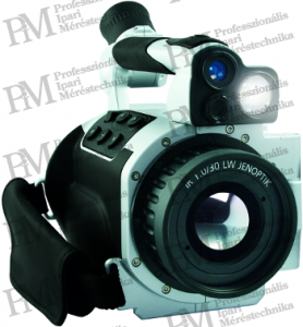
Although the micro-scan method cannot be considered fast (it takes 0.5 ... 1 second to create a high-resolution thermal image), it is currently the only method available to produce real pixel extra-large thermal images with maximum geometric resolution. Examples of such capable thermal cameras are the Jenoptik VarioCAM device families, which come with this optional function called Resolution Enhancement. With VarioCAM hr thermal cameras equipped with a 640x480 pixel detector, 1.23 million pixel thermal images can be created in micro-scan mode, and with VarioCAM HD thermal cameras equipped with a 1024x768 pixel detector, 3.15 million pixel - exclusively real measurement data-containing - thermal images can be produced. This allows for the most detailed measurements to be taken from very large surfaces without any subsequent montage.
To be continued!
Rahne Eric
Electrical Engineer (BME)
Vibration Diagnostic Expert
Thermography Expert
(Thermograph Level3)
pim-kft.hu
termokamera.hu
The content of the publication is protected by copyright, its (even partial) use, electronic or printed further publication is only permitted with the indication of the source and the author's name, and with the author's prior written permission. Infringement of copyright (Copyright) has legal consequences.
Copyright © PIM Professzionális Ipari Méréstechnika Kft.
2026 | Minden jog fenntartva
Impresszum | Adatkezelés