


Rahne Eric, B.Sc. in Electrical Engineering, founder of PIM Professional Industrial Measurement Technology Ltd., certified thermography expert (Thermograph Level 3), forensic expert
One of the youngest but presumably rapidly growing applications of thermography is assumed to be the quality control during solar cell manufacturing and the condition assessment of installed modules or even entire solar cell power plants. While, for example, U-I characteristic curve checks clearly indicate when efficiency is deteriorating, most of the fault locations and types cannot be detected through this method, especially not by breaking down the modules. In contrast, thermography, assuming proper execution, can localize fault locations and distinguish between various different types of faults. Especially in the case of large solar cell parks, this enables efficient operation and cost-effective maintenance. Typical Solar System Faults and Causes Faults in photovoltaic systems can lead to problems not only affecting their efficiency but also posing operational safety risks, including serious abnormalities that may cause fire hazards. Faults can be attributed to various reasons, ranging from manufacturing and transportation to installation and poor operational or meteorological influences. Some faults can be visually detected, but most require appropriate measurement methods for identification. Among these, the most common are the recording of U-I characteristic curves, the application of electroluminescence, and thermal imaging condition assessment technologies. The faults can be categorized as follows: - electrical connection faults (wrong polarity, contact failure, short circuit) - control faults (non-operational point operation, branch- or module-level bypass) - module-level faults (internal contact failure, shading, faulty module junction box, faulty bypass diode) - cell-level faults (breakage, hairline cracks, other aging, fracture, short circuit, PID) Among these, most electrical and fracture-type faults can be attributed to poor transportation and even more so to unprofessional installation. The shading problem is typically due to poor installation, poorly designed placement, or the encroachment of nature, overgrown plants, or surface contamination. Faults solely derived from aging are rare. To avoid misunderstandings, we would like to draw the reader's attention not to serious problems causing faults, but to some noticeable but insignificant visual phenomena. There are cases where the appearance of certain issues may suggest a serious fault to the untrained eye, but in reality, they have little impact on the operation and performance of the photovoltaic system.
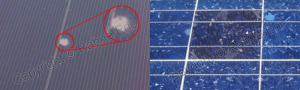

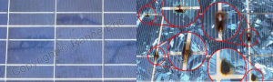
The damage caused by a stormy hailstorm or stone impact is often visually recognizable. However, it is not certain that the apparently undamaged other modules have actually survived the storm. Any additional hairline cracks that are not visible to the naked eye can only be revealed by applying one of the inspection methods presented below. Unfortunately, in many cases, these are only revealed after some time, following mechanical damage, when penetrating moisture or crack propagation causes the crystal itself to crack and short circuits or cell area detachments occur. Inspection of Solar Systems Based on Electroluminescence Images For recognizing faults and assessing their severity, the acquisition of U-I characteristic curves, as well as electroluminescence and thermography-based inspections, are much more accurate and efficient than visual inspection. While the evaluation of U-I characteristic curves can provide information about the system's condition and current capabilities only per branch, i.e., for multiple modules together, the other two methods are capable of localizing faults per module or even per cell and determining the nature and severity of the fault. Before discussing the application of thermography, let's say a few words about electroluminescence. The basic idea of the inspection method is that from an electronic perspective, solar cells represent a large-area light-sensitive diode. If they can produce current when exposed to light, then, with reverse operation, by applying current, they should be able to emit light. Cells that emit light over their entire surface in this way must also function well in their energy production state. Based on this, many manufacturers also perform checks during production. The light emitted by the solar cells is mainly in the short-wave infrared range. Accordingly, its observation is possible with short-wave thermographic systems, which, however, are usually used for rapid evaluation of cells integrated into the production line during production. On-site, mobile applications do not use such photon detector systems due to their weight, size, and high cost.
During on-site electroluminescence inspections, modified cameras, mostly single-lens reflex devices, are typically used. These should have a CMOS detector with a sufficiently wide spectral range, allowing the emission of solar cells to be detected by removing the built-in infrared filter and using a high-intensity lens that transmits short-wave radiation. Naturally, the measurement requires a long exposure time, up to several minutes, and the result is not calibratable. Since daytime sunlight is orders of magnitude greater than the radiation emitted in the reverse mode by the solar cells, electroluminescence images are preferably taken at night or during the day with the use of cover tents. Meanwhile, the modules or strings must be electrically disconnected from the system and provided with the necessary feedback for the examination. If the measurement is not desired to be carried out at night or with the use of tents during the day, the use of a true thermal camera is necessary. The latest CMOS-based short-wave thermal cameras, supplemented with appropriate filters, enable electroluminescence imaging to be performed during the day as well. Defects detectable by electroluminescence inspection: microcracks and fractures, cell surface detachment, detachment or increased resistance of surface and cell contacts, short circuits within cells or branches, or strings, PID damage. Thermographic Inspection of Solar Systems The cost of acquiring the required thermal camera for thermographic inspection, as well as the minimum required irradiance and other measurement difficulties, make it less competitive compared to the previously presented electroluminescence inspection. Nevertheless, thermography has its justification, partly because it does not require any rewiring or external power supply. This eliminates the need to carry a 18...30 kg DC power supply and implement power supply. On the other hand, thermography allows for the inspection of the largest areas proportionally to time, making it an essential technology primarily for large systems. While, for example, U-I characteristic curve checks can effectively indicate efficiency degradation, most types of faults and fault locations cannot be detected through this method, especially when modules are disassembled. In contrast, thermography, with proper implementation, can localize faults and distinguish various types of faults. Especially in the case of large solar cell parks, this enables efficient operation and cost-effective maintenance. Usual Application Conditions, Measurement Circumstances • operating state of solar cell systems in energy production mode • minimum continuous solar irradiance of 600 W/m2 • maximum 2/8 Cumulus cloud cover, light cumulus clouds • rain and snow-free conditions, no water or snow on the cells • maximum wind force of 4 Beaufort (20 ... 29 km/h) (= moderate wind) • ensuring adequate field of view and geometrical resolution • providing photographic and GPS-coordinated documentation for larger systems Common Faults Detectable by Thermography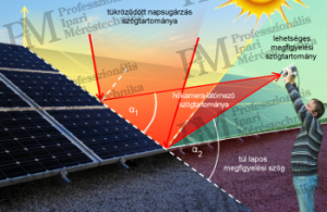
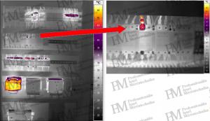
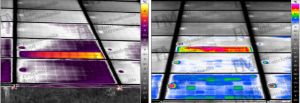
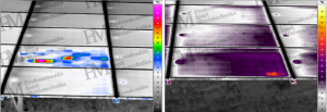
While on the left "overview" image the loose contact appears with a temperature of only 38°C and does not seem like a fault, on the right, based on the thermographic detailed recording with appropriate geometric resolution, it turns out that its actual temperature is already above 58°C. (20°C measurement error!) Thermographic sample recordings for contact faults / loose connections
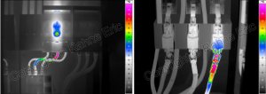
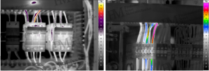
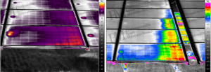
Thermographic sample recordings for undersized electrical wires
Thermographic sample recordings for transformers and electrical transmission lines
![left: transformer; right: transmission line with fault [source: Infratec]](/images/4040/szolar7-300x106.png)
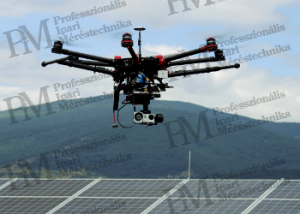
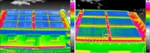
Thermographic survey of large-scale solar systems with drones The nature of the measurements listed in the introduction, the quantity of related recordings, and the difficulties related to field of view and viewing angle specifically lead to the application of aerial thermography. A typical example is the thermographic survey from an airplane or helicopter in environmental protection, environmental monitoring (e.g., for water management, agriculture, or wildlife counting), large-scale archaeological and geological research. The aerial survey of solar systems, primarily large-scale photovoltaic power plants, is becoming increasingly common, facilitated by the appearance of drones with increasing payload capacity and easier application, even capable of automation. (Of course, it is important to remember that the use of drones is subject to strict regulations, legal requirements, and additional technical and legal risks may arise.)
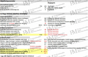
With a thermal camera of adequate resolution and correct parameter settings (measurement frequency, observation field of view, as well as flight altitude and speed), the quality of thermal images shown in the following figure (effectively evaluable) can be obtained. The complexity of requirements and parameters (and their interplay) is so multifaceted that discussing it in this presentation (or article) is unfortunately not possible.
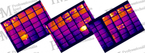
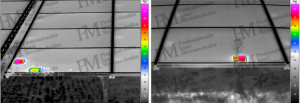
Thermographic sample recordings for faults in photovoltaic systems
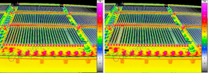
Of course, not only for photovoltaic systems but also for solar thermal systems, thermography is an effective tool for monitoring and troubleshooting. Assuming proper implementation, it can localize faults and distinguish between various different fault phenomena. Especially in the case of vacuum tube collectors, detecting (unauthorized) heat build-ups is key to their efficient operation and cost-effective maintenance. General survey of solar thermal systems The biggest difference compared to "classic" thermographic applications is the requirement for intense sunlight during outdoor measurements. This is completely contrary to the emphasis in almost all other thermographic applications, where we avoid conducting thermographic measurements in sunlight and especially under direct sunlight on the object being measured due to sunlight reflection and object heating. However, in the inspection of solar thermal systems, sunlight is essential to reveal temperature differences caused by fault phenomena. Common faults detectable via thermography • At the level of pipe systems: • Inadequate, damaged insulation • Leaks, poorly closing valves, shut-off valves, etc. • At the level of flat plate collectors, vacuum tube collectors: • Vacuum loss or insulation faults • Operational problems, incorrect sizing • Damage (weather, vandalism) Requirements for surveys Sunlight reflecting off glass surfaces can only be counteracted with carefully chosen observation angles, as discussed in the case of solar cell systems. Consequently, the positioning of the thermal camera at height is problematic in the current applications. Therefore, it is unavoidable to climb onto the roof with a ladder or use a work platform or a huge telescopic rod. More convenient, especially for larger systems, is the drone inspection of their collectors. Another significant issue relates to the geometric resolution of the thermographic measuring equipment. The maximum measurement distance must be carefully selected to provide a good overview of the system while ensuring the necessary geometric resolution for accurate temperature detection of the detail being observed (e.g., the vacuum tubes). Thermographic sample images of faults in solar collectors (vacuum tube systems)
The source of the (abbreviated) text and thermal images: Eric Rahne: THERMOGRAPHY - theory and practical measurement technology 656 pages (A4, color), 303 figures, 452 images, 754 thermal images, 50 tables ISBN 978-963-87401-6-8 (printed book, no electronic edition) For more information: www.termokamera.hu Eric Rahne (PIM Kft.) pim-kft.hu, termokamera.hu
The content of the publication is protected by copyright. Any (even partial) use, electronic or printed re-publication is only permitted with the indication of the source and the author's name, and with the author's prior written permission. Violation of copyright (Copyright) will result in legal consequences.
Copyright © PIM Professzionális Ipari Méréstechnika Kft.
2026 | Minden jog fenntartva
Impresszum | Adatkezelés