


Eric Rahne, BSc in Electrical Engineering, Level 3 Accredited Thermography Expert (PIM Ltd.)
A few years ago, we already discussed in detail on the pages of this magazine the issues related to thermographic inspection of electrical equipment: however, it cannot be denied that this inspection method is becoming increasingly widespread due to its efficiency and reliability in detecting electrical faults. Thus, by revisiting some elements of the previous series of articles, we attempt to provide a brief overview of this subject area once again.
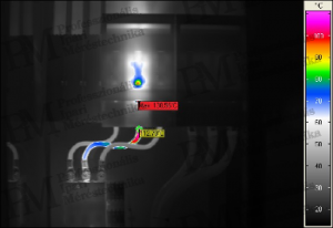
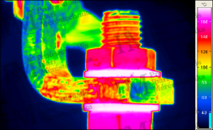
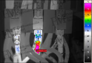
Thermographic condition assessment of electrical equipment is based on the fact that undersized or damaged conductors, poor connections (due to increased transitional resistance), and most often electrically faulty devices heat up to higher temperatures than usual (allowed).
The greatest advantage of thermography is that measurements can be safely carried out from a distance - even on equipment operating at several kV - without affecting the operation of the device being inspected.
The range of detectable problems can be illustrated with the following list:
When conducting measurements, it is advisable and important to follow certain rules. Among these, the following can be highlighted.
The question often arises where to draw the line between perceived heating being considered faulty or even dangerous. It is particularly difficult to decide on this issue when thermographic surveys are conducted at significantly lower current levels than the maximum load.
Primarily (to avoid this problem), it is advisable to accept that thermographic condition assessments of electrical equipment should only be carried out when at least 50% of the rated load is present. Only very severe faults can be detected at 30% load.
Accepted threshold values, as well as decision rules (at least 75% load)
Threshold values compared to environmental temperature
Heating* <20 °C: normal
Heating* <40 °C: to be checked
Heating* >40 °C: to be checked urgently
Heating* >60 °C: critical
(* above the ambient temperature)
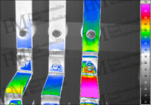
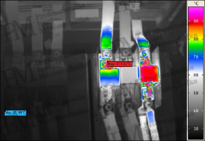
Threshold values for differences between phases
Deviation** <5 °C: okay
Deviation** <20 °C: to be checked
Deviation** >20 °C: to be checked urgently
Deviation** >40 °C: critical
(** between phases)
Threshold values depending on the insulating material
Rubber-insulated cables: max. 60 °C ***
PVC-insulated cables: max. 70 °C ***
Silicone-insulated cables: max. 180 °C ***
(*** absolute temperature values)
Other threshold values
Electric motors (measured on cooling fins): depending on the type max. 60...80 °C ***
Plastic covers: depending on the material: max. 50...75 °C ***
Magnetic switches: typically max. 85°C ***
Transformers: typically max. 85°C ***
(*** absolute temperature values)
Note: under lower loads, lower limits than all the above values are valid.
Estimated heating under nominal load
Heating occurs due to the energy loss in the form of heat generated by the transient resistance of the tested electrical device (cable, rail, etc.). The device then dissipates this power through heat radiation, convection (towards the air), and heat conduction towards the connected elements. Since the expected heating under higher loads (whether current or voltage) is influenced not only by the load- and temperature-dependent resistance of the device or contact but also by the expected stronger heat conduction, heat radiation, and convective heat dissipation, determining the resulting heating would require very complex mathematical relationships.
In a steady state in a (assumed to be infinitely long) rail or conductor, the expected temperature can be calculated based on the following equation:, but since the equation required for this purpose is quite complicated due to the difficult-to-access material properties, we recommend using the following estimation instead:
Simplified heating estimation for nominal load (estimation used by the author of the article)
If we assume that the temperature increase between the load at the time of measurement and the nominal load is so small that the material-specific resistance change due to temperature (increase) can be neglected, and neither the current crowding factor nor the heat transfer factors change significantly due to the observed device temperature increase, then all these factors can be considered constant in the previous equation. (This can be applied in case of temperature increases of a few tens of °C. However, for larger temperature changes, these simplifications can lead to significant errors, so the equations below CANNOT be applied.)
By applying the above simplifications, we obtain the relationship that the absolute temperature of the object rises above the ambient temperature in proportion to the ratio of the nominal and measured voltage values, as well as in proportion to the square of the ratio of the nominal and measured currents, depending on the difference between the measured and ambient temperatures of the object. The estimated temperatures can then be compared with the threshold values listed on the previous page.
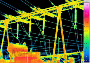
Important: when inspecting substations and overhead lines, all conditions for outdoor measurements must be strictly adhered to. Measurements can be carried out at night (preferably under a cloudy sky) or during the day in very thick, completely closed - but rain-free - cloud cover. (From experience, we prefer conducting measurements at night.) Also, it should not be forgotten that we mostly want to determine the temperature of metallic objects - thus objects with significant heat radiation-reflection capabilities - without contact. To minimize the effects of interfering radiation, it is best to measure when there is none. (For example, helicopter power line inspections carried out under the condition of clear daytime visibility - i.e., sunny weather - are pointless unless the aim was a sightseeing flight.)
From a measurement technology perspective, geometric resolution is also critical: for measuring the increase in the transient resistance of overloaded ropes with a diameter as small as 18 mm at a height of 30 m and their connections, a geometric resolution of 0.2 mrad (or even better) is required, hence a large telephoto lens is necessary. Some faults in insulators may still be detectable with a weaker geometric resolution.
Rahne Eric
Electrical Engineer (BME)
Vibration Diagnostic Expert
Thermography Expert
(Thermograph Level3)
pim-kft.hu
termokamera.hu
The content of this publication is protected by copyright, and its (even partial) use, electronic or printed re-publication, is only permitted with the indication of the source and the author's name, and with the author's prior written permission. Violation of copyright (Copyright) will have legal consequences.
Copyright © PIM Professzionális Ipari Méréstechnika Kft.
2026 | Minden jog fenntartva
Impresszum | Adatkezelés