


Eric Rahne, B.Sc. in Electrical Engineering, Level 3 Accredited Thermography Expert (PIM Ltd.)
Thermal cameras suitable for contactless temperature measurement have undergone rapid development in recent years, so that today, during a purchase, it is not the lack of suitable types that may cause trouble, but the overwhelming variety of options. Therefore, it is time to review the types and characteristics of these instruments from a professional perspective, and to organize the current selection based on some important technical parameters. These determine the application areas of the devices, as well as the expected measurement accuracy and the available thermal image quality. In the first part of our article, we discussed the detector types of thermal cameras, reviewed the significance of frame rate and pixel resolution, and clarified the advantages and disadvantages of image resolution enhancement techniques. This article continues by discussing the characteristics of thermographic lenses and delving into the evaluation capabilities of modern thermal cameras.
The most important property: thermographic lenses cannot be made of glass, but only of material suitable for the wavelength range of the thermal camera. Therefore, you cannot buy a thermal camera and then attach an optical microscope lens just because you want to measure very small objects at the moment. Similarly, a long-wave thermal camera lens cannot be mounted in front of a mid-wave thermal camera (and vice versa). In both cases, you would find that you cannot measure any radiation. In the case of long-wave thermal cameras, the lens material is typically germanium, which is coated with a special anti-reflection layer, achieving transmission factors of over 99%. (So, do not remove dirt from the optics with chemicals or abrasive cleaners!) Effect of Lens Diameter on Measurement Capabilities The larger the diameter of an optical lens of a thermal camera (more precisely: its aperture), the more radiant energy reaches the thermal sensor surface. The measure of the optical system's brightness (here: intensity of transmitted infrared radiation) is the f-number, which is the ratio of the focal length to the aperture diameter of the lens. Naturally, the smaller the f-number, the larger the lens diameter and the greater the energy input to the sensor, resulting in increased sensitivity and accuracy. But beware: the larger the lens diameter, the more it deviates from the ideal optical system model - the Gaussian optics. This leads to increased imaging errors (e.g., image distortion), which can only be counteracted with increasingly sophisticated lens shapes. If you want to support the above with some numbers, compare the most common "category" of bolometer thermal cameras. The small lenses of Low-Cost thermal cameras allow sensitivity of up to 100 mK at a frame rate of 50 Hz; to achieve better thermal resolution (e.g., 80 or 60 mK), the integration time needs to be increased - thus reducing the frame rate to 30, 25, or only 9 Hz. The large lenses of professional thermal cameras, depending on the capabilities of the camera manufacturer, can provide thermal resolution of up to 30 mK at a frame rate of 50 Hz (or even up to 240 Hz). Of course, it is not just that the lens of a Low-Cost thermal camera costs at most a few hundred thousand forints, while for professional devices, the prices of thermographic optics are above one million forints. Necessity and Variety of Exchangeable Lenses In thermographic measurements, beyond ensuring the correct observation field size for evaluation, the most important aspect is to provide the necessary geometric resolution for accurate temperature detection. For example, with a "standard" lens offering a 2 mrad geometric resolution, objects (or object details) of at least 30 mm in size can be reliably detected from a distance of 5 m. To measure smaller objects, either a smaller measurement distance or a different optics must be chosen. (Otherwise, the thermographic image would not be able to show the temperature of the small object we are interested in.) So, if we replace the aforementioned "standard" lens with a telephoto lens, we can measure objects of 15 mm in size from a distance of 5 m with a 1 mrad geometric resolution. Primarily for professional thermal cameras, there is a wide range of interchangeable lenses, which often connect to the thermal camera with a bayonet for easy exchange. The lenses also have electronic coding so that the thermal camera can automatically recognize which lens we are using and load the calibration data file associated with the lens. This is necessary because the calibration of each thermal camera is always done together with the installed lens to determine and correct the characteristics of the lens and the thermal camera together. Therefore, if we change the lens, a different calibration data file is required for radiation detection correction. (From this, it follows that a lens purchased later entails manufacturer re-calibration of the thermal camera. Also, even among identical thermal cameras, "identical" lenses cannot be exchanged without consequences.)
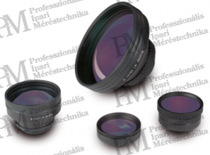
The most common lenses and their roles (or "side effects") are presented in the following list: • Standard Lens Depending on the pixel resolution of the thermal camera detector, with these lenses, geometric resolutions of approximately 20x15° ... 30x25° fields of view can achieve resolutions of 2.4 ... 0.6 mrad. • Telephoto Lens Compared to standard lenses, typically, with the dimensions of the field of view halved in both dimensions, geometric resolutions that are twice as good (numerically halved) can be achieved. There are also "larger" telephoto lenses that offer reductions in the size of the field of view and geometric resolution by a quarter or even a tenth, thereby improving the geometric resolution to the same extent.

• Wide-angle lenses Compared to standard lenses, typically doubling the field of view in both dimensions is achievable, but at the same time, the geometric resolution is halved (numerically doubled). There are also so-called super wide-angle lenses that can quadruple the size of the field of view (while degrading the geometric resolution to a quarter). • Close-up lenses, macro lenses The primary role of these lenses is to reduce the minimum measurement distance of standard lenses or telephoto lenses, allowing very small objects to be measured from very close distances that meet the requirements of geometric resolution. • Microscope lenses Microscope lenses are used for measuring special small objects, and their imaging capabilities are similar to optical microscopes. Their disadvantages, in addition to their large size, weight, and cost, include minimal depth of field.

We would like to draw attention to the often completely erroneous use of wide-angle lenses! For example, if our concern was that while adhering to the limit of geometric resolution, from a specified maximum measurement distance, only a part of the object to be measured (e.g., a switchgear cabinet) could be captured in each thermal image, then the application of a wide-angle lens acquired to increase the field of view not only does NOT solve our problem but worsens our situation. This is because due to the wide-angle lens resulting in a doubled field of view in both directions, the halved geometric resolution limits our measurement to a distance of at most half of the previous distance. Consequently, the field of view of our measurement does not actually increase (as it remains the same size), but with image distortion, the viewing angle of the object surface can be quite skewed, especially towards the edges. This further negatively affects the accuracy and evaluability of our measurement. (Note: Wide-angle lenses are mostly justified in indoor building thermography. Before their application in other professions, careful consideration is required to ensure that despite the achieved larger field of view, no other potentially more serious optical or metrological disadvantages arise.)
Thermography - as a "visual" non-contact temperature measurement method - involves first collecting measurement data (digitalized radiation intensity values from each pixel). These values need to be processed appropriately, mathematically corrected (converted to temperature), and then displayed either immediately during the measurement (in the thermal camera) or during later evaluation. The requirements for evaluating thermal images vary greatly depending on the specific measurement task. While in some cases determining the specific temperature of each pixel is sufficient, in other cases, correcting the emissivity value of each pixel or even capturing and evaluating entire image sequences is necessary for the desired temperature correlations and processes (e.g., in the form of temperature-time diagrams). Often, data evaluation and display as temperature values need to be done during the measurement (even in real-time). Live evaluation practically means that it is part of the operating process of the thermal camera, integrated into the handling of the camera. The following table lists the "automatic" auxiliary functions and real-time evaluation possibilities built into or that can be integrated into modern (professional) thermal cameras (without claiming completeness):
| Function | Explanation |
|
Autofocus |
focusing the thermal image based on the steepest temperature gradient |
|
Automatic measurement range |
setting the measurement (calibration) range according to the current measurement |
|
Automatic thermal image scaling |
scaling the display based on the currently measured min/max values |
|
Temperature color scale |
displaying multiple selectable color and/or grayscale scale values |
|
Pixel temperature display |
live display of the temperature of the central pixel of the thermal image |
|
Cursor temperature display |
live display of the temperature of one or more movable cursors |
|
Min/Max temperature display |
displaying the location and value of the coldest/hottest pixel |
|
Multi-surface temperature display |
displaying average, peak, or minimum values of defined surfaces |
|
Display of isotherms |
highlighting pixels within a defined temperature range in a single color |
|
Differential image display |
depicting temperature differences compared to a reference thermal image |
|
Thermal image averaging |
averaging multiple thermal images (noise reduction, sensitivity enhancement) |
|
Temperature alarm |
visual/acoustic alarm in case of minimum or maximum exceedance |
|
Automatic storage |
triggered automatic measurement storage depending on temperature value |
|
Composite image display |
continuous (live) projection of visual image (photograph) and thermal image |
|
Storage of thermal image series | Thermal image data storage in the thermal camera (without PC connection) |
|
Digital sound recording |
Adding acoustic commentary to the stored thermal image data |
|
GPS data management |
Geospatial assignment of ground and aerial vehicle thermal images |
|
Remote control capability |
Remote control capability of thermal camera functions (with or without cable) |
The more of these functions we find in our thermal camera, the more versatile its applicability and the more convenient and efficient on-site work becomes. From the mentioned evaluation possibilities, we would highlight the temperature-dependent start of measurement storage, which often greatly assists in recording thermal events that are not predictable in advance. In the case of fast processes, the image series recording function provides the solution, taking advantage of the unbeatable benefit of thermography: the ability to record thermal processes that occur in fractions of seconds. Thanks to the built-in composite image display in the thermal camera (referred to as "fusion" by some companies), there is no longer a need to take separate photos for documentation, which represents a significant time-saving opportunity. Moreover, when projecting the thermal image and photograph onto each other in this way, the relationships between object temperatures can be documented more clearly and easily than ever before.

Rahne Eric, B.Sc. in Electrical Engineering (BME), Vibration Diagnostic Expert, Thermography Expert (Thermograph Level3) pim-kft.hu, termokamera.hu
The content of this publication is protected by copyright. Any (even partial) use, electronic or printed republication is only permitted with the indication of the source and author's name, and with the prior written permission of the author. Violation of copyright will result in legal consequences.
Copyright © PIM Professzionális Ipari Méréstechnika Kft.
2026 | Minden jog fenntartva
Impresszum | Adatkezelés