


Eric Rahne, B.Sc. in Electrical Engineering, Level 3 Accredited Thermography Expert (PIM Ltd.)
Our series of articles on thermography aims to provide insight into the incredible versatility of thermography and its theoretical and practical limitations, drawing from Rahne Eric's 650-page specialized book titled "THERMOGRAPHY - theory and practical measurement technology." The current topic is aerial thermography on energy systems.
It is self-explanatory why thermography is invaluable in this context. By using it, solar power plants with power outputs of several MW can be surveyed relatively quickly. While I-V characteristic curve checks can show when efficiency is declining, fault locations and types are often not detectable through this method, even when breaking down to individual modules. Thermography, on the other hand, assuming proper implementation, can pinpoint fault locations and differentiate between various types of faults. Especially in the case of large solar cell parks, this enables efficient operation and cost-effective maintenance.
The inspection of solar cell systems is similar to thermographic condition assessments of electrical equipment. The essence is that undersized or damaged cables, poor connections due to increased transient resistance, and in most cases, electrically faulty devices heat up beyond the permissible (or usual) temperature. The evaluation templates and thresholds used for electrical equipment inspections on connections, cabling, distributors/collectors, regulators, and converters are also applicable here. However, these cannot be applied to individual solar cells or modules. Therefore, this chapter specifically deals with the theoretical background and practical knowledge required for solar cells.
The main difference compared to previously presented thermographic applications is the requirement for intense sunlight to conduct outdoor measurements. This is in stark contrast to the emphasis in almost all other thermographic applications, where measurements should not be performed in direct sunlight and especially when the object being measured is under direct sunlight. This is to avoid the reflection of sunlight and the object heating up. In the case of inspecting solar cell systems, however, direct sunlight is necessary to reveal temperature differences caused by faults. The detection of these differences is hindered by sunlight reflection on glass surfaces, which can only be counterbalanced by carefully selecting the observation angle.
Standard Application Conditions and Measurement Circumstances
at the level of electrical system elements:
at the level of solar cells and modules:
Before delving into the detailed discussion of thermographic measurements, inspections, and results related to solar cells, let's review some relevant information. First and foremost, let's look at some background information on solar cells and solar cell systems, which are significant contributors to fault phenomena and related thermal effects.
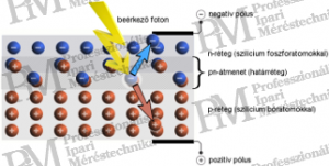
Operation of Solar Cells
Solar cells utilize the internal photoelectric effect. The current leading cell types are based on silicon (Si), where the layer directed towards light is doped with phosphorus (P) atoms to form an n-layer, and the "back" layer is doped with boron (B) atoms to form a p-layer. Due to the electric field at the pn-junction, electrons split from incoming photons accelerate towards the negatively charged n-layer of the cell, where there is an excess of electrons. Meanwhile, the holes created by electrons in the p-layer cause an electron deficiency. By connecting the two layers through an electrical load, the electrons return to the p-layer, where the recombination of electron-hole pairs occurs (Figure 1).
Typical Structure of Solar Cell Modules (Solar Modules)
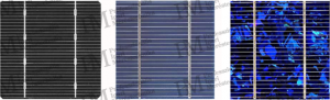
Due to the size of silicon wafers originally intended for electronics manufacturing, solar cells are mostly 6 x 6” (156 x 156 mm) in area. The voltage achievable with a single cell is approximately 0.5 V DC. Since this would be insufficient for energy production due to voltage drops on the wires, 60 cells are connected in series in a so-called solar module or panel. This configuration provides around 30 V DC. Polycrystalline solar modules assembled in this way can reach a current of 8 A under 1000 W/m2 irradiance.
For more efficient energy transfer, a voltage greater than 30 V is required, so it is common to connect up to 24 modules in series in solar module arrays. The voltage of such a module string or branch is already 720 V DC. However, this also means the series connection of 1440 solar cells, posing the risk that a single damaged, non-operational cell will affect the performance of all cells in the entire module string. This is because the damaged cell acts as a resistor instead of a current generator, thus becoming a consumer.
To mitigate this issue, it is common practice to create 3 internal branches, so-called substrings, in each module, which are connected in parallel with individual bypass diodes. If a cell fails in one of the internal branches, thanks to the diode, this branch does not reduce the current flowing through the other branches of the module, it simply drops out as an energy producer. While not ideal, as 20 cells drop out due to one faulty cell, it is still better than limiting 1440 cells.
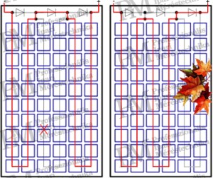
If an internal branch fails due to a circuit break or shading, the diode of the affected branch as shown in figure 2 comes into operation. The output voltage of the module drops to one-third of the total module's nominal voltage, further decreasing by 0.3 to 0.9 V due to the diode voltage drop. Therefore, a nominally 30 V DC output voltage module in such a case can only provide 19.1 to 19.7 V DC. This is a loss, but still better than the entire module failing.
The faults in solar systems can manifest not only in the form of problems that reduce efficiency but also pose operational risks, including serious abnormalities that may cause fire hazards. Faults can be attributed to various reasons, ranging from manufacturing to transportation and installation, as well as poor operational or meteorological influences. The next part of the article series will cover these issues and methods for investigating faults.
Rahne Eric (PIM Ltd.)
pim-kft.hu
termokamera.hu
The content of this publication is protected by copyright, and its (even partial) use, electronic or printed republication is only permitted with the indication of the source and author's name, and with the author's prior written consent. Violation of copyright will result in legal consequences.
Copyright © PIM Professzionális Ipari Méréstechnika Kft.
2026 | Minden jog fenntartva
Impresszum | Adatkezelés