


Eric Rahne, B.Sc. in Electrical Engineering, Level 3 Accredited Thermography Expert (PIM Ltd.)
Errors in photovoltaic systems can cause not only efficiency-reducing problems but also operational safety risks, including serious abnormalities that may lead to fire hazards. This topic is discussed drawing from the author's 650-page specialized book titled "Thermography - Theory and Practical Measurement Technology."
Errors can be attributed to various reasons, ranging from manufacturing and transportation to installation, poor operational practices, or meteorological influences. Some errors can be visually detected, but most require appropriate measurement methods for identification. Among these, the recording of the I-V characteristic curve, the application of electroluminescence, and thermographic condition assessment technologies are the most common.
Errors can be categorized as follows:
Among the above, most electrical and fracture-related errors can be attributed to poor transportation and even more so to unprofessional installation. The shading problem is typically due to poor installation, poorly designed placement, or encroachment of nature, overgrown vegetation, or surface contamination. Errors solely derived from aging are rare.

Image 1: Contamination or oxidation trapped during production inside a thin-layer cell, usually without significant power loss. Image 2: Different cell discoloration in polycrystalline modules, with no performance-reducing effect. Image 3: Delamination in monocrystalline modules, due to overheating or chemical reaction between the bonding layer and the soldering flux, typically without significant power loss. Image 4: Barely noticeable traces of a serious hailstorm. The true extent of damage is only revealed later when water starts to penetrate the layers of the cells, causing oxidation and eventually complete cell failure. Image 5: Visual snail trails on modules indicating hairline cracks, water penetrating the cell layers, causing oxidation and eventual complete cell failure. To avoid misunderstandings, we would like to draw attention here not to serious problems causing faults but to some noticeable yet insignificant visual phenomena. There are cases where the appearance of certain issues might suggest a serious fault to the layman, but in reality, they have little effect on the operation and performance of the photovoltaic system. These include contamination or oxidation trapped inside a thin-layer cell during production (Image 1), different cell discoloration in polycrystalline modules (Image 2), delamination in monocrystalline modules, whether from overheating or due to a chemical reaction between the bonding layer and the soldering flux (Image 3). The signs indicating the most serious issues in the solar system are much less conspicuous. This includes barely noticeable traces of hail damage (Image 4), where the true extent of damage is only revealed later when water starts to penetrate the cell layers, causing oxidation and eventually complete cell failure. The phenomenon usually involves significant power loss, potentially resulting in the complete failure of the affected cell or module. Another sign indicating a more serious issue is the "visual snail trail" on modules (Image 5), indicating hairline cracks. In this case, water penetrates the cell layers, causing oxidation and eventually complete cell failure. This usually involves significant power loss, potentially resulting in the complete failure of the affected cell or module. The damage caused by a severe hailstorm or stone impact is often visually recognizable. However, it is not certain that the apparently undamaged other modules have truly survived the storm. Any additional hairline cracks that are not visible to the naked eye can only be detected by applying a specific inspection procedure. Unfortunately, in many cases, it is only after the occurrence of mechanical damage, when the penetrating moisture or the spreading of cracks causes the crystal itself to crack and short circuits, as well as cell area detachment.
For recognizing errors and assessing their severity, the U-I characteristic curve recording, as well as electroluminescence and thermography-based inspections, are much more accurate and effective than visual inspection. While evaluating the U-I characteristic curve can provide information about the system's condition and current capability only for a group of modules, the other two methods are capable of localizing faults and determining the nature and severity of the fault on a per-module or per-cell basis.

The basic idea of electroluminescent inspection is that from an electronics perspective, solar cells represent a large-area light-sensitive diode. If they can generate electricity when exposed to light, then with reverse operation, by applying current, they should be able to emit light. For those cells that emit light over their entire surface in this way, they should also function well in their energy production state. Based on this, many manufacturers also perform in-process checks during production.

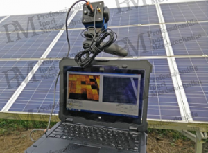
The spectral range of light emitted by solar cells is mainly in the short-wave infrared range. Therefore, its observation is possible with short-wave thermographic systems, which are typically used for rapid evaluation of cells integrated into the production line during manufacturing, but not for on-site mobile applications. Photon detector systems are used more in on-site electroluminescent inspections due to their weight, size, and high cost. Modified cameras, mostly DSLR cameras, are used in these cases. Equipped with a CMOS detector with a sufficiently wide spectral range, these cameras, along with an infrared filter removal and the use of a short-wave radiation-passing, high-intensity lens, enable the detection of solar cell radiation emissions. Of course, the measurement requires a long exposure time, up to several minutes, and the results are not calibratable.

Since daytime solar irradiation is orders of magnitude higher than the radiation emitted by the cells in reverse bias mode, on-site electroluminescent images are preferably taken at night or during the day with the use of cover tents. Meanwhile, modules or strings must be electrically disconnected from the system and provided with the necessary feedback for the inspection. If neither night inspection nor tent solutions are feasible, the use of a genuine thermal camera becomes necessary. The latest CMOS-based short-wave thermal cameras, supplemented with appropriate filters, allow electroluminescent imaging to be performed during the day as well.
Defects detectable by electroluminescent inspection:

Thermal imaging inspection may not seem competitive compared to the previously presented electroluminescent inspection due to the cost of acquiring a thermal camera, the requirement for minimal irradiation, and other measurement difficulties. However, thermography has its justification, partly because it does not require any rewiring or external power supply. This eliminates the need to carry a 18-30 kg DC power supply and implement power supply. Furthermore, thermography allows for the inspection of the largest areas proportionally to time, making it an essential technology primarily for large systems. To be continued. Eric Rahne (PIM Ltd.) pim-kft.hu, termokamera.hu
The content of this publication is protected by copyright. Any (even partial) use, electronic or printed republication is only permitted with the indication of the source and the author's name, as well as with the author's prior written permission. Violation of copyright (Copyright) will result in legal consequences.
Copyright © PIM Professzionális Ipari Méréstechnika Kft.
2026 | Minden jog fenntartva
Impresszum | Adatkezelés